
Control LED in Arduino board.
Prior to the beginning…
In fact, I can not use English well. But, I just try to use English for this posting.
Why? we are the one! I want you to hear my voice at opposite side of the earth.
You know what? it is so amazing that you can hear my voice(thinking) at everywhere.
So, I hope you can hear.
If you can not understand my words or if there are wrong sentences or grammars,
please let me know, I will try to fix it!
Thanks, my global friends(it’s you I’m talking to!).
1. Review
Previously, we installed Arduino IDE and checked Arduino electrical circuit.
Sorry? Did you say there is no electrical circuit in your head?
No worries, we can check it in Arduino website easily.
(http://www.arduino.cc → RESOURCES → PRODUCTS → Clink your Arduino type → DOCUMENTATION → SCHEMATICS)
2. What can we do for first Arduino project
Now, I am ready to start Arduino! yay! Do you? (please, just say YES!)
I’m excited!!! (Even thouth, I know that I will tear my hair out when I face with problem! hahaha)
What can we do as our first project!? Hm…
Hang on, there are LEDs on Arduino Mega Board! Green and Yellow LEDs!
3. Check the electrical circuit of Arduino Mega
I wonder whether I can control LEDs or not.
Let’s check the electrical circuit!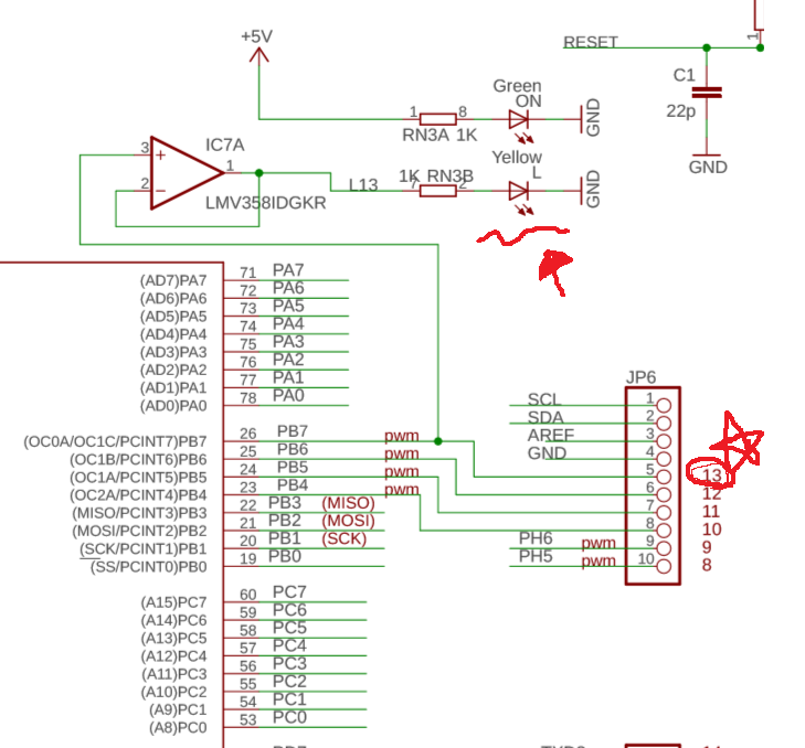
As you can see, Green LED is connected to 5V with resistor.
Maybe Green LED indicates Arduino board status.
Becuase Green LED is not connected with Atmega port, we can not control it.
On the other hand, Yellow LED is connected with PB7. It means we can control! Maybe!
It is so good for beginner like me.
4. Execute IDE and Check ‘Blink’ example
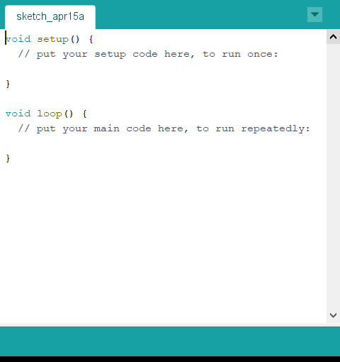
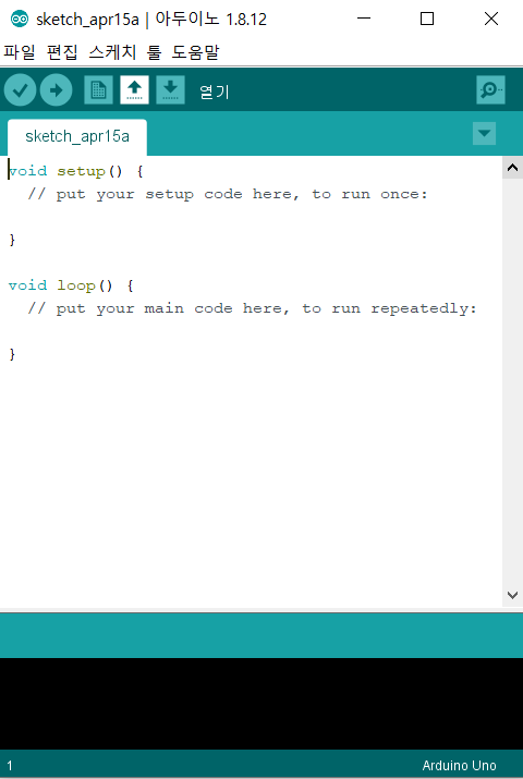
Let’s execute IDE icon. There are many examples.
Among them, let’s load ‘Blink’ example from Arduino IDE.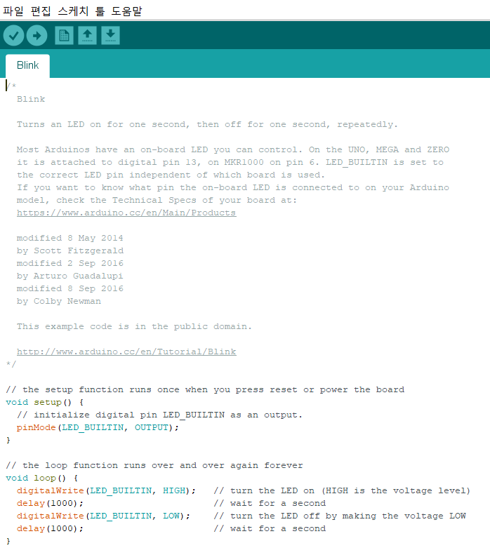
Can you see it?
There are two functions in this example, setup() and loop().
Usually, setup() is for initializing Arduino.
It this example, “pinMode(LED_BUILTIN, OUTPUT);” is in setup().
5. Check the example code
“pinMode(LED_BUILTIN, OUTPUT);” ??????????? what is it? (No!!! my hands are going to my hair!)
Check Arduino website again.
(http://www.arduino.cc → RESOURCES → REFERENCE)
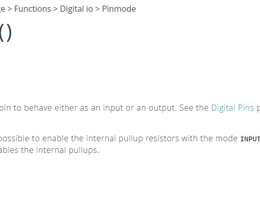
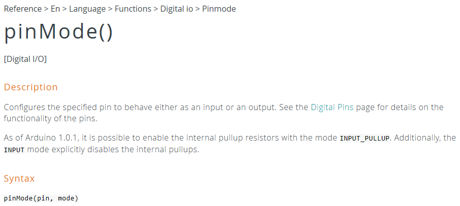
There is explanation of pinMode()!
But…OMG…this page is full of alphabet……..I am not familliar with English yet.
It’s OK. One of my best friend will help me. His name is Dictionary.
“pinMode()” is for Input/Output setting one of the pins.
By writing this in setup(), We can control pin of ATmega 2560.
In other words, we are ready to control Yellow LED.
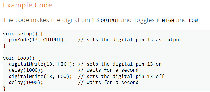
6. Predict the LED operation
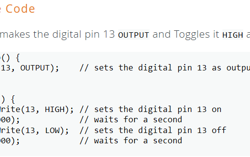
“pinMode(LED_BUILTIN, OUTPUT);” → I will use 13 pin as a output pin!
So, signal will come out from this pin as I program.
- digitalWrite(13, High); → Set 13 pin High
- delay(1000); → waits for a second. The number means milli-second. (ms : milli-second)
(milli-second(ms) means 0.001 sec! Thus, 1000ms means 1 second.) - digitalWrite(13, Low); → Set 13 pin Low.
- delay(1000);
As a result, LED On – 1sec delay – LED Off – 1sec delay – LED On – 1sec delay … This actions will be repeated!
7. Confirm the LED operation in Arduino board
Let’s confirm!!!
By changing the number which in delay(), we can control LED Turn On/Off period.
In my case, I changed the number from 1000 to 2000.
Wow…look at this Yellow LED. What a beauuuuuuuuuuuuutiful! (This is not because I control it. Never, Never! kkkkkkkk)
Practice make us better!
Okay. this posting is ended!
How did you feel? Was it Okay?
Let’s do our best for upgrade ourselves!
Then, See you soon, my friends!